

It shouldn't be too hard to build a simple robot to auto-dial safe combinations. All you need is a servo to rotate the dial and some way of sensing when the correct combination has been entered. And since robots are infinitely patient, it can just brute-force combinations until it finds the correct one.
How long will that take? Well, the safe has 100 numbers per dial, and the combination is 3 numbers. That means 100^3 or 1,000,000 possible combos, right? Actually no. First, locks have mechanical tolerance. When entering a number into the dial, your number-entering precision needs to be something like ± 1 increment from the correct number. Actual tolerance depends on the exact model of lock, going down to about ± .5. I don't know exactly what model of lock is on the safe, but it appears to be made by Sargent and Greenleaf, and looking at their catalog of modern locks for reference, I settled on ±1. So, that cuts the number of possible combinations by a factor of 8, bringing it down to 125,000. Additionally, according to the manual, one should never set the third number to anything 95-20, because it can stop the lock from working correctly. This brings the total number down to 92,500. Much more reasonable. Supposing it takes 6 seconds to enter a combination (I'll explain why it takes so long later), that's 6.4 days to try everything. So it should average something like 3.2 days to open. That is still a pretty long time, but as long as I'm not sitting there entering combinations, who cares?
On to the hardware. Here's the basics of how it works:
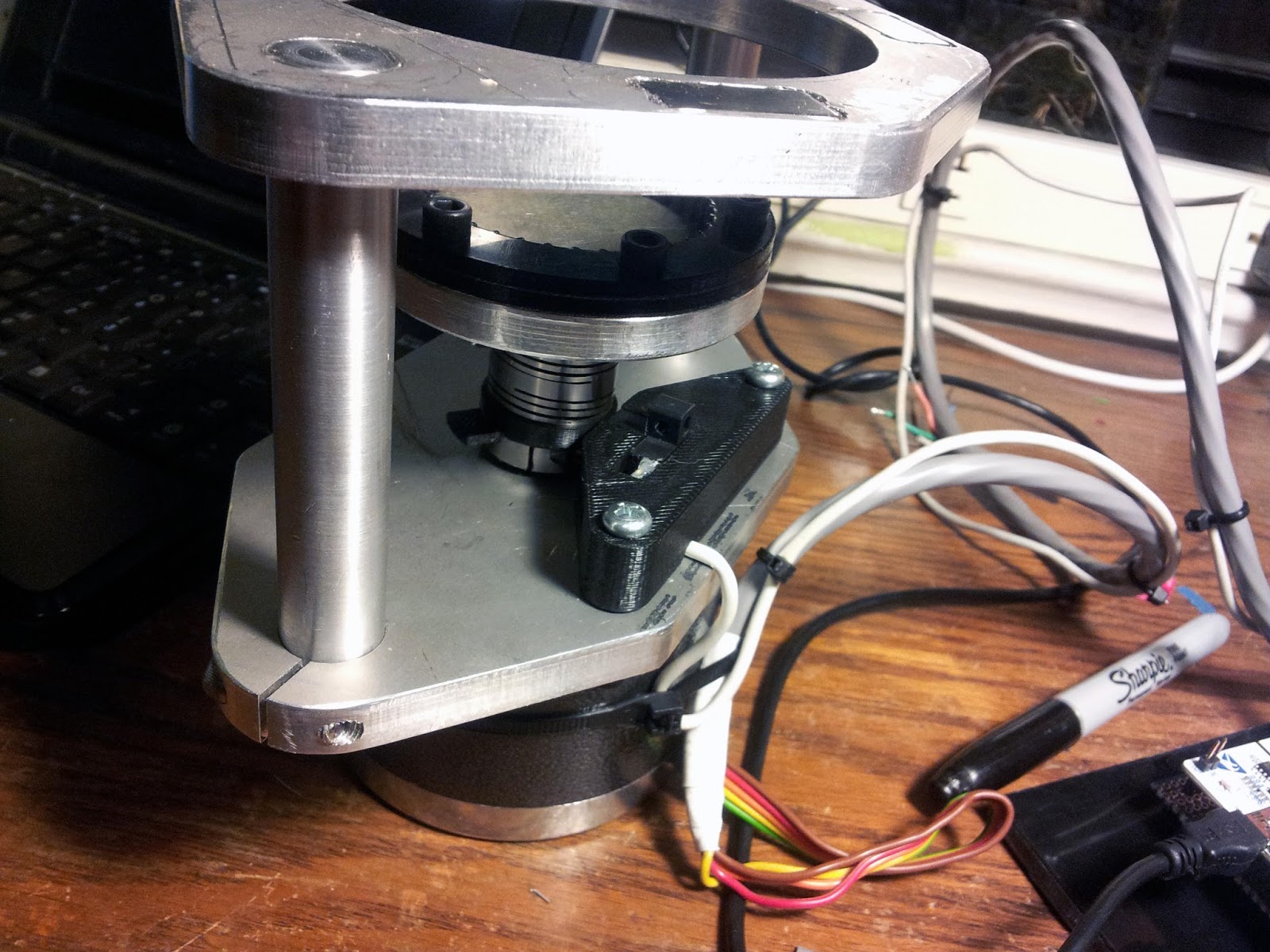
The device will magnet on to the door of the safe. A coupling with a spline matching that of the dial will mesh with the dial to connect it to a motor. I'm using a giant stepper motor. Now I want to be very clear, I hate stepper motors. They're terrible. Servos all the way. However, I didn't have any motors with appropriate low-speed torque and backlash-free gear-down on hand, so I didn't have much choice but to use a stepper motor. I grabbed the biggest one I could, which I scavenged out of some old lab equipment a while back. The stepper is powered by a (also scavenged) stepper driver, which is controlled by an STM32 Nucleo F411RE. I found about these things through Bayley, and they're great. $10, lots of computing power, and compatible with the mbed compiler, which I am already very familiar with. This is in turn connected to a netbook which logs attempted combinations and sends me an email every 1000 tries and when it thinks the lock has been opened.
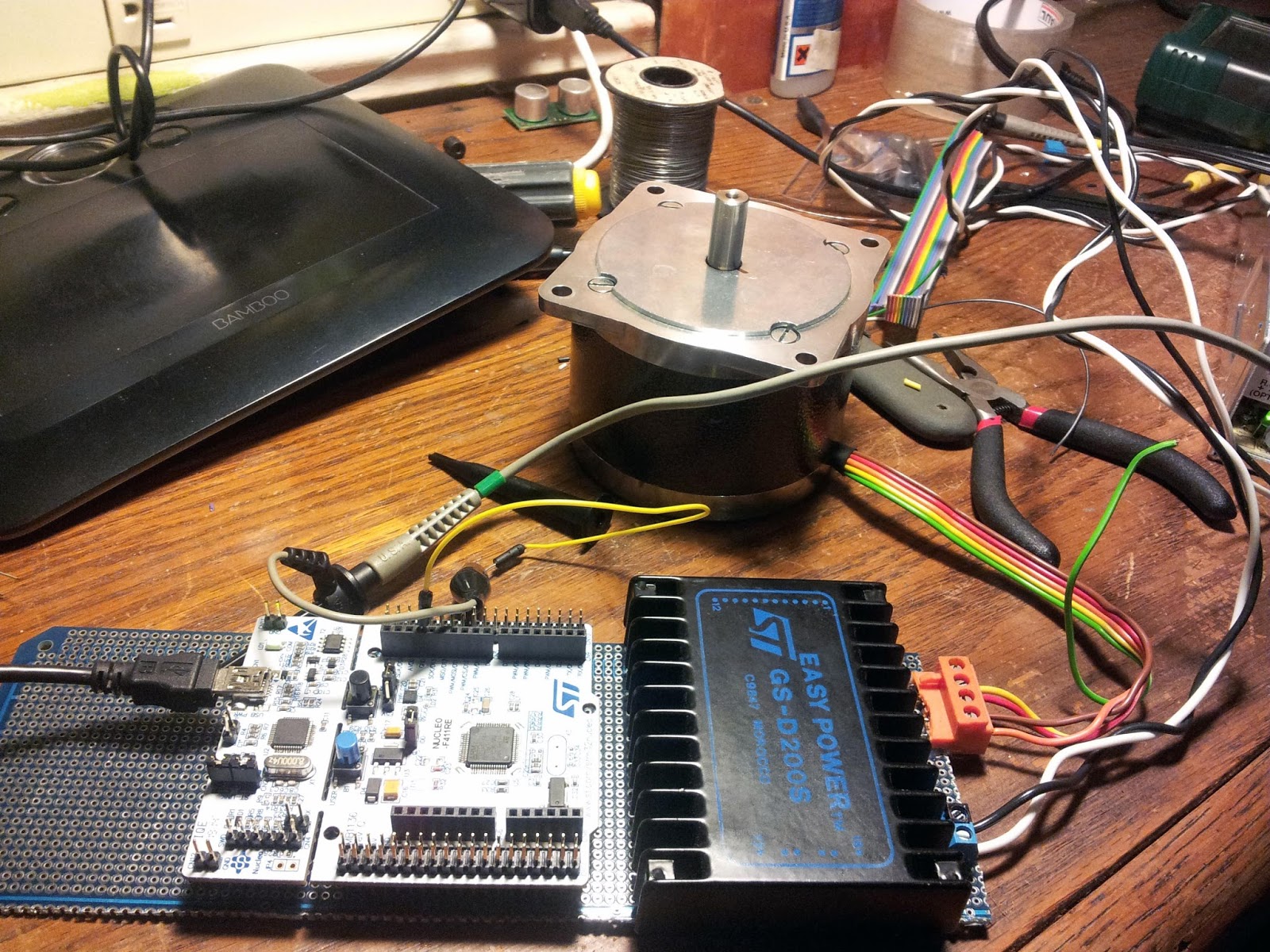
Here's the motor, microcontroller, and stepper driver. To start out, I used this Easy Power GSD200S, because some x-ray equipment MITERS crufted a couple months ago had a bunch of them. This driver could only do half-stepping, so everything was really noisy. When first testing out the machine, there was a noise complaint from someone living two floors above the desk. I later swapped this stepper driver out for something a bit nicer.
The easiest thing to do with a stepper motor is just command it constant step rate for constant velocity motion. When starting and changing directions, though, this demands nearly instant velocity change, which doesn't work that well for either the motor or the lock. To make things smoother, I implemented some acceleration control which adjusts the delay between steps to approximate constant acceleration.
This isn't too difficult to do. First define some starting velocity (because no one wants divide-by-zero errors): v_sart, in steps per second. The pulse period, dt, required to move the motor at v_start is just 1/v_start. Say the motor should accelerate at rate a, in steps/seconds^2. The first time interval, dt_1, is equal to 1/v_start. After accelerating at rate a for time dt_1, the motor's velocity should be v_start + a*dt_1. So the next pulse duration, dt_2, should be 1/(v_start + a*dt_1). Repeat this process, substituting in the previous step's velocity and period, and you can generate a set of pulse durations that approximate constant acceleration of the motor. Mirror that set of pulse durations about its end, and you have a constant acceleration, constant deceleration trajectory between two points. The smaller the steps are, the smaller you can make v_start, and the better the approximation is.
On to some hardware building.
Some metal plates for the structure where milled on the MITERS CNC mill:
 |
| T-nuts can be step clamps too |
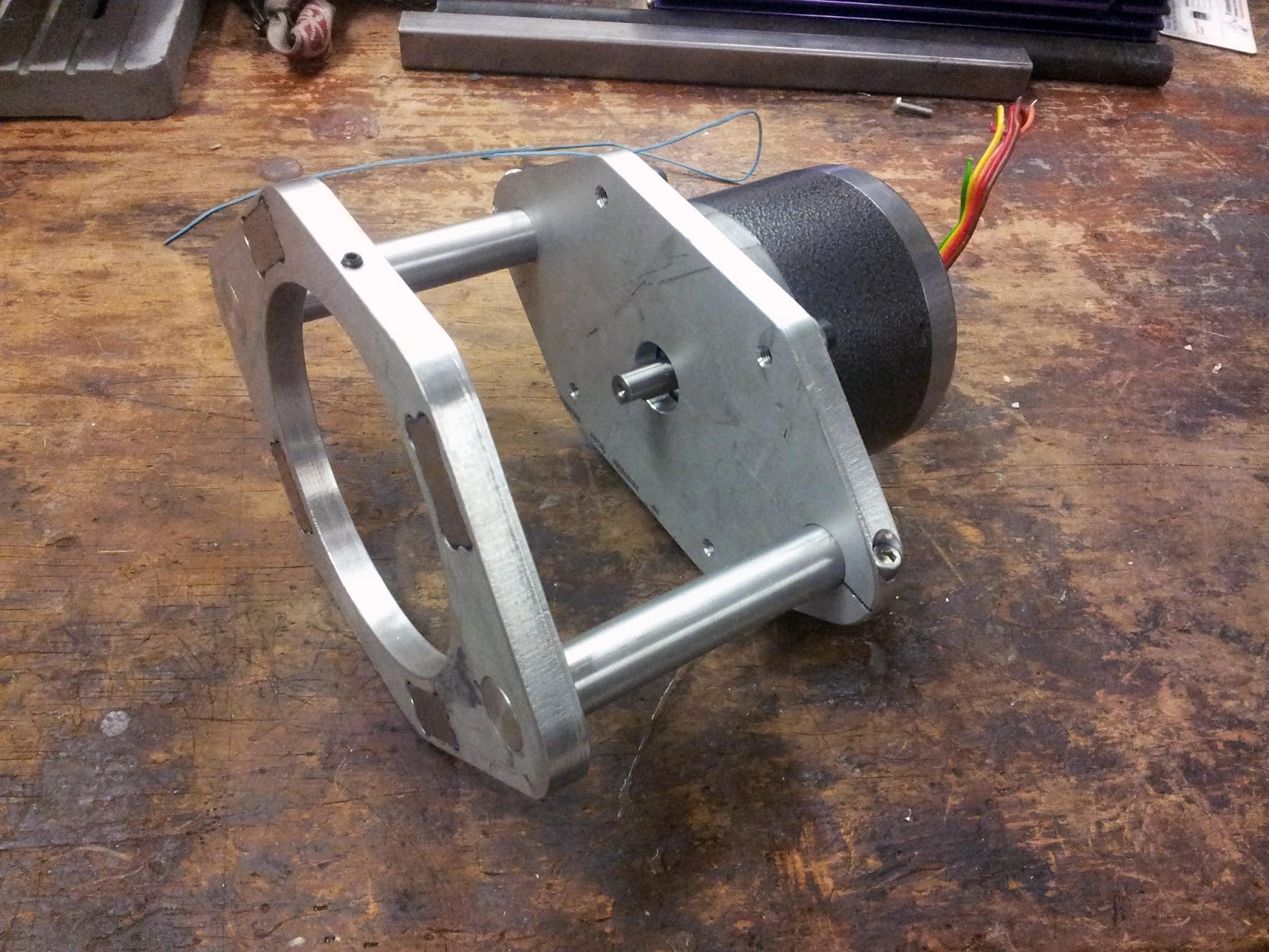
The front metal plate has four large neodymium magnets press-fit into it.


Two aluminum rods are press-fit into the front plate. A set screw in the front can be tightened into the ring around the lock's dial, to prevent anything from rotating. The spacing of the motor can be adjusted using the two clamps around the shafts on the motor plate.
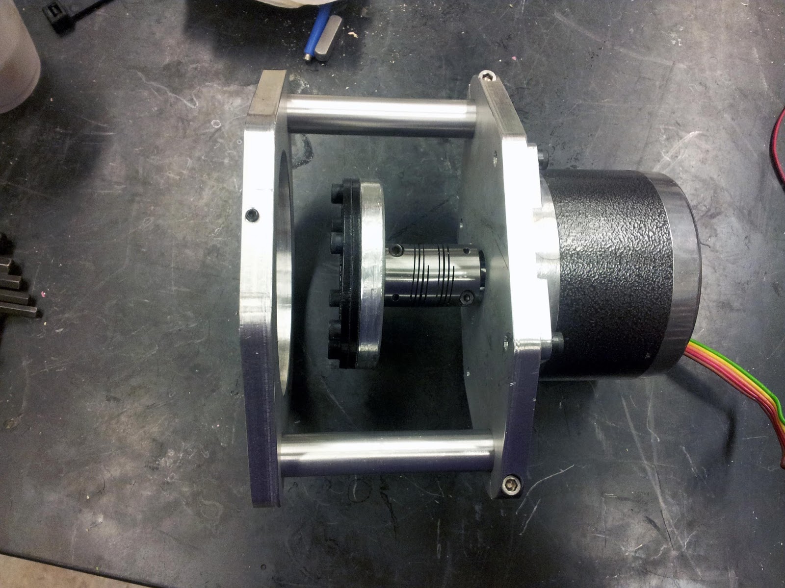
A laser-cut delrin spline meshes with the dial:
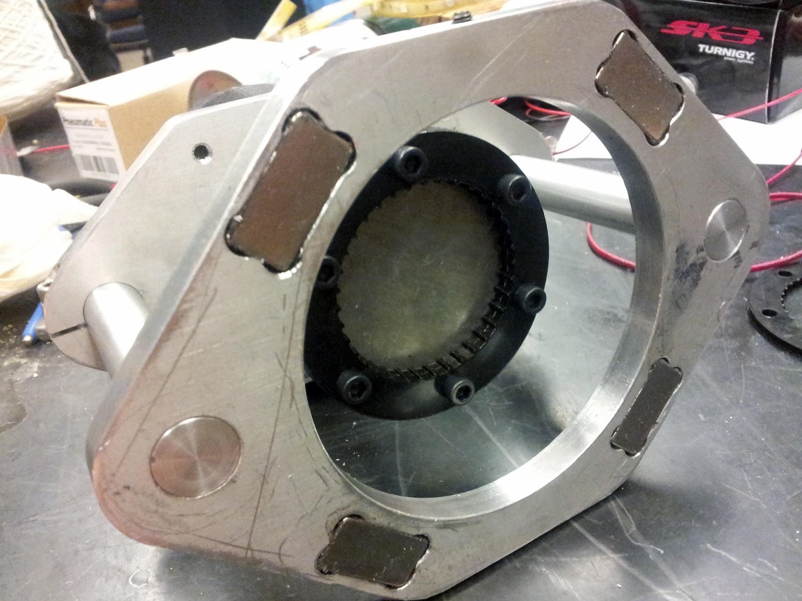
The dial-spline is coupled to the motor with a flexible shaft coupling to compensate for lack of concentricity and wobble in the dial.
To sense when the correct combination has been entered, there is a one count per revolution encoder on the shaft, made from an optical limit sensor. After entering the correct combination into one of these locks, you turn the dial clockwise until it locks up (around 95). At this point the stepper will stall. The sensor detects when the stall has occurred, so the microcontroller knows the lock is open.
Here it is installed and running for the first time:
(video credit to Danny Ben-David)
There are a couple points to note.
- It's very loud. This is caused by the half stepping limitation of the stepper driver used, and lack of mechanical isolation between the motor and frame. I fixed the latter by adding some squishy rubber between the motor and it's aluminum plate, and securing it with Structural Zip Ties rather than steel screws. Stepping noise was reduced by switching to a fancier stepper driver with 32x microstepping.
- It's not very fast, especially on the first counter-clockwise rotation. This particular lock gets extremely stiff on the fourth turn around the dial. I had to slow down the stepper to stop it from skipping steps during that part of the rotation. This could be solved with a higher voltage power supply.
Hopefully before the next report the safe will be open. Current progress is around 2%
Hey. First of all - sorry for my english. I've got a few questions about your stepper project.
ReplyDeleteFirst of all - how do you connect oscilloscope to stepper for measure current for stepper?
Second - could you write some more about your acceleration algorithm (or post some code)?
The scope isn't measuring stepper current, it's displaying the step signal to the stepper driver. However, you could measure stepper current on a scope by putting a small known resistance in series with a phase, and looking at the voltage drop across it.
DeleteThe explicit function that executes a step command is as follows:
void fstep(int steps){
float pulse_train[steps]; //Create an array to store the pulse durations
for(int i=1; i<steps; i++){ //Fill the array with zeros
pulse_train[i] = 0;
}
pulse_train[0] = 1/v_start; //Starting velocity v_strt
pulse_train[steps-1] = 1/v_start; //Ending velocity v_start also
for(int i = 1; i<steps/2; i++){
float vel = (1/pulse_train[i-1]) + acc*pulse_train[i-1];
float dt = 1/vel;
pulse_train[i] = dt;
pulse_train[steps-(i+1)] = dt;
}
for(int i = 0; i<steps; i++){ //Limit maximum velocity
if (pulse_train[i] < (1/v_max)){
pulse_train[i] = pulse_train[i-1];
}
step = 1;
wait(pulse_train[i]*.5);
step = 0;
wait(pulse_train[i]*.5);
}
delete [] pulse_train;
}
Did you eventually crack the safe?
ReplyDelete